Build
The module is not hard to build. The following instructions will guide you through the process. Jump straight to the iBOM if you want to check the needed parts and you are familiar with building stuff.

the needed parts.
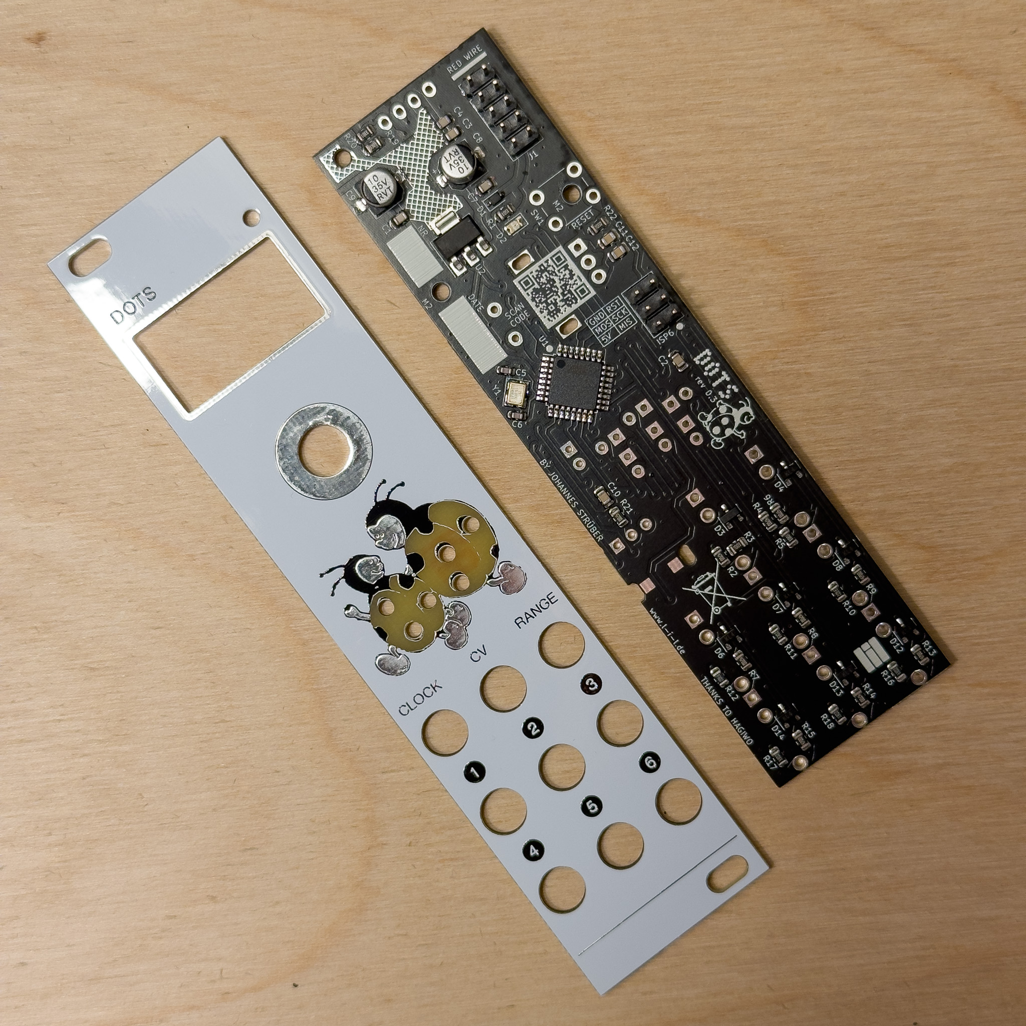
After ordering the pcbs and the needed parts We can start to build the module. The following process shows the build with presoldered smd parts. If you choose to solder the smd parts yourself feel free to share your experience.

pcbs with presoldered smd parts
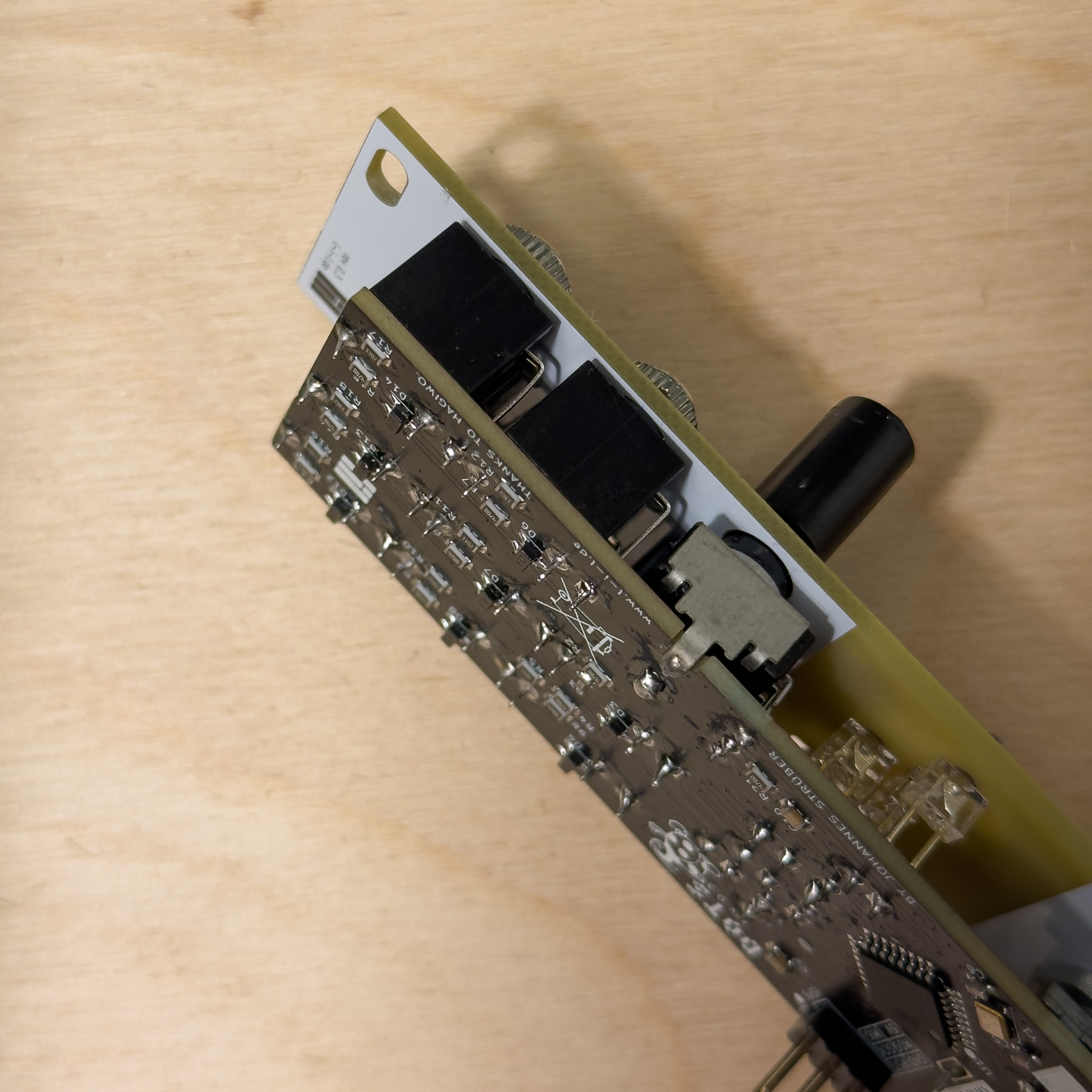
With the audio jacks all placed in the front and main pcb we can start to solder them in place.
After that try to bend one leg of the potentiometer around the pcb to maintain the width of the module. Solder it in place.

soldered jacks and potentiometer
Next step is to solder the red clock led light close to the main pcb.
Move on to the small white leds which are placed on the front pcb. Turn the pcb around and solder the leds. Keep in mind that the orientation of the leds is important.
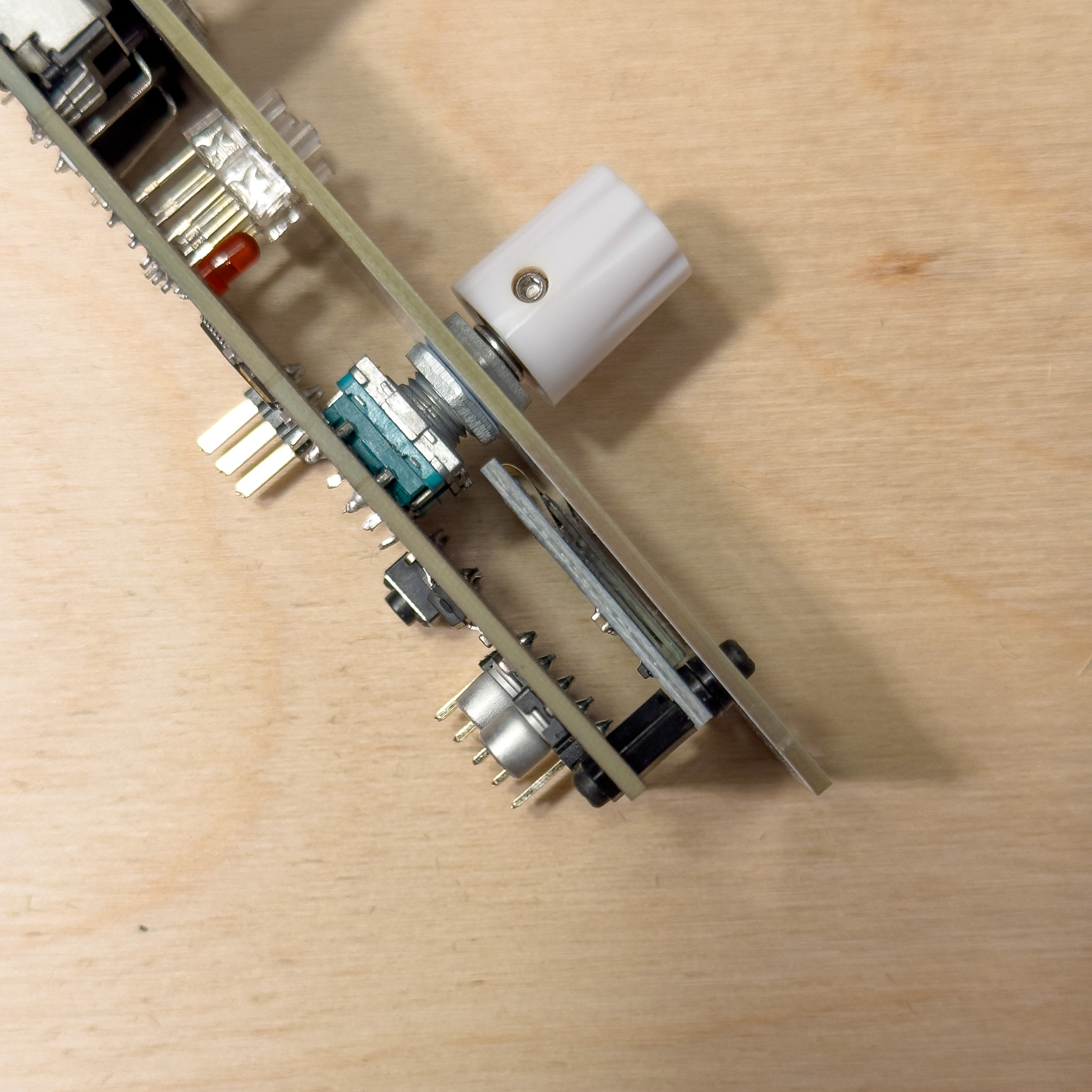
Again with the front pcb on solder the rotary encoder in place. I put one nut above and one below the pcb to keep the encoder in place.
Solder the OLED Screen legs to the main pcb with the pins being flat on the pcb. Recheck the orientation and rotation of the screen to match the front panel cut out
Screw the screen tight via some spacers and the holes in the front- and main pcb.

OLED with spacer, encoder with nuts and the leds
With everything in place check for shortages between GND 5V -12V and +12 V. Also check if everything is mounted and every through hole is soldered.
Now screw the audio jack screws, the potentiometer knob and the encoder knob in place.

Thats the finished module
Check again for shortages and if everything is in place. Connect the power and check if the screen lights up. If everything is fine move to the next step and flash the firmware.

Thats the backside with everything mounted.